C5 Corvette Climate Control Panel Repair

Corvette-Climate-Control
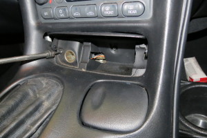
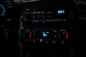
The air conditioning display on a C5 Corvette is known as a Climate Control Panel or Climate Control Module interchangeably. This module houses all the computerized control and operating software to carry out your automatic climate control functions. A very common problem with the air conditioning displays on these Corvettes is that they either display dimly, sometimes sections are dim, they don’t display at all, or they don’t function at all. Any of these problems may be constant or intermittent. Some C5 Corvette owners have reported that when these problems occur hitting bumps in the road or tapping the climate control panel may cause the symptoms to worsen or improve.

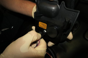
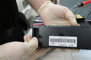
The image above is of the automatic climate control module for a C5 Corvette. If your module looks like this one and has a blank display while installed in the car and turned on you may be wondering what could be wrong.

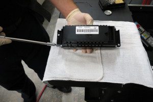
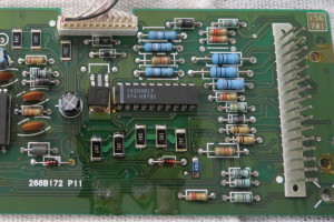
Overwhelmingly, these problems are caused by faulty solder joints for power supply resistors on the module’s internal circuit board. In the past it was popular to simply replace these modules and few repair shops like ours existed that knew how to repair them. Now they have been discontinued and this repair service is growing in popularity. Why should you choose us?

  • We Are Local to the Tampa Bay Area
  • We Offer Same Day Service
  • We Offer Full Service Corvette Support
  • We Offer Real World Corvette Experience
  • We Value Our Customers

Remove Console Rear Nut Covers

Open the console and find the oval shaped nut covers towards the rear The rear nut covers simply pop out with a flat tool. I use non marring nylon trim tools.

rear-nut-covers

Remove Active Handling Panel

Using a flat tool Remove the panel housing the active handling switch switch Simply work the tool under the panel and twist A wire will still be attached don’t pull the panel too roughly

handling-panel

Disengage A/H Switch Connector

Disengage the active handling switch connector by squeezing the release tab and pulling away from panel

switch-connector

Remove Power Port

Remove the power port/cigarette lighter This will require the removal of the electrical connector by pulling it away from the port Early models may have a screw on retainer for the port Late Models have a plastic bodied port with locking tabs that must be turned and maneuvered through a corresponding slot in the console

power-port

Slide the Center Console Rearward

Slide the center console as far rearward as possible For convertible slid the console under the rear waterfall it will move enough to remove the radio bezel later

console-rearward

Position Gear Selector and Brake Lever

Position the gear selector as far rearward as possible Pull the parking brake lever up

brake-lever

Remove Temperature Sensor Cover

Remove the cover for the inside air temperature sensor The cover is simply snapped in place they are easy to brake the tabs on so be gentle

sensor-cover

Remove the Radio Bezel Screw

Remove the screw under the inside air temperature sensor cover with a T15 tool

bezel-screw

Remove Screw Beside Cigarette Lighter

There are two screws behind the door for the ashtray and cigarette lighter One is to the left of the cigarette lighter Like the previous screw it is also T15

screw-beside-cigarette-lighter

Remove Screw Behind Ashtray

Fully removing the ashtray will expose the last screw This screw is also T15

screw-behind-ashtray

Remove the Radio Bezel

With the console door closed, the gear selector back, and the parking brake lever up remove the radio bezel There are still tabs holding the bezel to the instrument panel, pull rearward to disengage the tabs The steering wheel may need to re-positioned to find the right angle to extract the bezel Watch the bottom of the bezel as it passes over the leather top of the console door. On coupes I prefer to pass the bezel over the console with the door closed to avoid potential damage to the door mechanism. On convertibles I prefer to pass the bezel by an open console door as there is less room due to the body colored waterfall.

radio-bezel

Remove Bezel Connectors

Remove the cigarette lighter electrical connector from behind the radio bezel piece Also, remove the inside air temperature sensor electrical sensor connector if equipped

bezel-connectors

Remove Right CCP Screw

Remove the 7mm screw from the right side of the Climate Control Panel

right-ccp-screw

Remove Left CCP Screw

Remove the 7mm screw to the left of the Climate Control Panel

left-ccp-screw

Remove CCP from Dash

Simply pull the CCP rearward to remove from the dash and expose the electrical connector

ccp-from-dash

Disconnect CCP Connector

Squeeze the blue tab, then pull and wiggle the electrical connector free from the CCP

ccp-connector

Remove CCP Case Half Screws

Remove the 4 3/16″ screws from the rear of the CCP hold the case together

ccp-case-half-screws

Remove Rear Circuit Board

Carefully apply pressure to the male terminals of the electrical connection to push the rear board free from the case

rear-circuit-board

Rear Board Removed

The rear board should now be free of the case and we can now see the resistors we need to re-flow the solder joints for

board-removed

C5 CCP Power Supply Resistors

There are 8 power supply resistors positioned around the board There are 2 different rear board designs There are always 8 resistors They are rectangular, black, and stenciled “241”

power-supply-resistors

Prep the Joints with Flux

We use common rosin flux to prep the joints and clean the solder and prevent oxidation as we re-flow the joints

joints-with-flux

Prep the Resistors with Flux

Apply a dab of flux to all the solder joints of the resistors

resistors-with-flux

Re-Flow the Solder Joints

Using a soldering iron (we use a 40 watt Weller with a small chisel tip) and a secondary tool apply pressure to a resistor pushing it into the board with the secondary tool Heat the solder joints with the iron and flux until the joints has been completely melted and reformed Repeat for the second joint on the same resistor Repeat for all seven remaining resistors

solder-joints

Re-install and Enjoy!

Reverse the dis-assembly and removal instructions and enjoy your fully functional full brightness climate control panel

re-install

Accessibility Toolbar